Making My Own Control Arms

blangoman

Junior Member
Messages
76
I guess you mean their rear tie rod spherical bearing? The original is a SKF bearing, they are £15 each and are perfectly good for the job!
Im just in the middle of refreshing the GS also. Have you a link to the exact SKF bearing online, do they come with the boot also? Many Thanks, Si
 

Zep

Moderator
Messages
9,275
Im just in the middle of refreshing the GS also. Have you a link to the exact SKF bearing online, do they come with the boot also? Many Thanks, Si

They are SKF GE15C. You need to reuse the original spacers and boots. If you boots are past it you can probably find replacements, perhaps someone else has had to do this?
 

Paulrv2

Junior Member
Messages
87
I bought a pair of the Formula Dynamics aftermarket tie rods as well. Just arrived today and look pretty good.
 

blangoman

Junior Member
Messages
76
Thanks for the SKF reference. It was actually the only boots that had perished in the desert heat . The joint has no play, i guess its a tough call to get the FD aftermarket set because of a boot.
 

lambertius

Banned
Messages
341
Thought I would throw out an update.

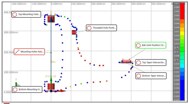
Despite some issues with the plague getting in the way of everything, I managed to get my co-ordinate geometry report for both the upper and lower control arms. If I'm lucky I'll be able to get a material sample off on Tuesday, if not it will be a month before I can get another chance.

So below are some screen shots of the report I received. It is a bit low tech these days, but a lot cheaper than 3D scanning and for simple shapes it is good enough.

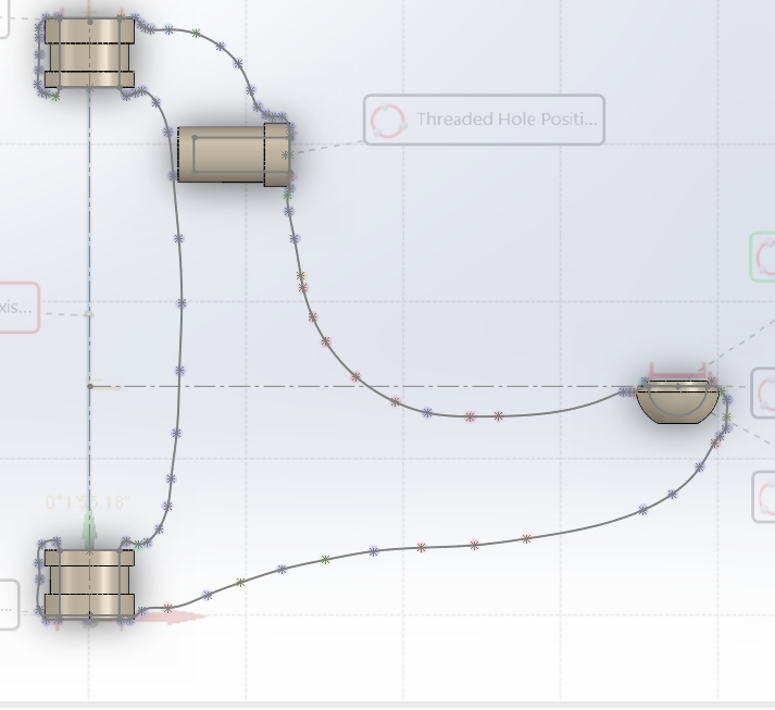
You get a co-ordinate system with a bunch of data points. Further on in the report some of the specific call outs that are named are given specific values that I can apply. Most important is that I'm given the centre co-ordinates for all the mounting points.
68370

From this I can generate exact mounting positions in CAD
68371

I can choose how to join those points in anyway that I want. For my own arms I'll be changing the sizing of the tie rod, ball joint and bushing points so that I can just pull some common catalogue parts.

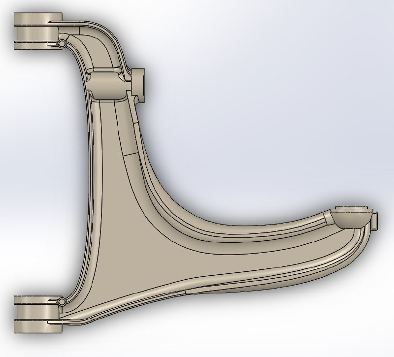
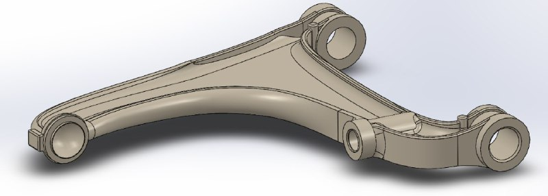
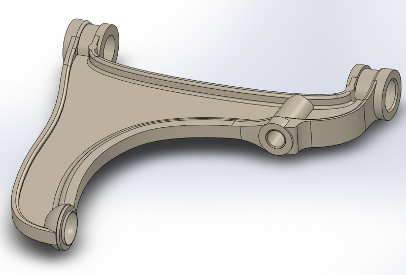
However before I do that, I'd like to understand exactly what the engineers at Fiat were doing, so I've used my report to generate an exact copy of the lower control arm. Once I have my material properties report from SGS I'll be able to simulate the part to see if there was anything specific they were trying to achieve. I'm not expecting to find anything though as it is a very simple application of double wishbone suspension.

There are some variations between the model and reality - for example I haven't included the casting line (but it is included in the model geometry, just inactive). Though I have enough information to include all the details it just simply isn't necessary or useful. The below model needs a few more details but is fundamentally correct. The round edges are a quite time consuming.
68373
 

Paulrv2

Junior Member
Messages
87
I’ve ordered the pattern part lower front and rear arms plus replacement front upper ball joints for my car. Want to get rid of the constant clunks and knocks when driving on Adelaide roads. The work could have waited a bit but decided to bite the bullet and get it done so I enjoy the benefit. Are old parts of any use to you when replacement fitted?
 

lambertius

Banned
Messages
341
I’ve ordered the pattern part lower front and rear arms plus replacement front upper ball joints for my car. Want to get rid of the constant clunks and knocks when driving on Adelaide roads. The work could have waited a bit but decided to bite the bullet and get it done so I enjoy the benefit. Are old parts of any use to you when replacement fitted?

Yes please! It will give me a few more samples to test the ball joint injection with before I go fitting it to my car! Once you've had it all done, send me a PM and I'll send you my address. I'm happy to cover the postage!
 

Paulrv2

Junior Member
Messages
87
Ok, I’m sure quite a few (including me) would like to know whether the injection approach works for these parts. I’ll have a full set of front and rear lower arms plus front upper ball joints that you can have.
 

lambertius

Banned
Messages
341
Ok, I’m sure quite a few (including me) would like to know whether the injection approach works for these parts. I’ll have a full set of front and rear lower arms plus front upper ball joints that you can have.

Your noble sacrifice to the elder Gods will not go unrewarded.
 

lambertius

Banned
Messages
341
68470

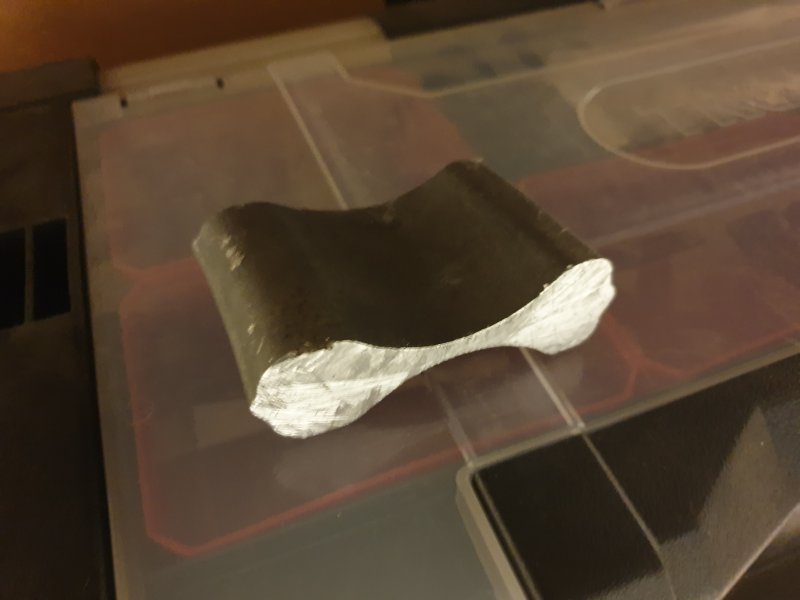
A sample for the lab - hopefully I can get this out tomorrow! There is no obvious crystallisation from drop forging, but then I don't work with magnesium so I'm not sure how it should look. It turns into a powder when heated with a jet lighter, so I do think its a mag alloy of some kind.
 

lambertius

Banned
Messages
341
I finished modelling the lower control arm. Is it perfect? No, but it is as good as it will ever get without using a tool like Catia or 3D scanning. I'm confident that this represents accurately the lower control arm.

68523
68524

My wonderful fiancee has taken my sample to SGS, so hopefully late next week I'll get some material data.

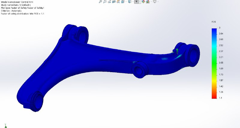
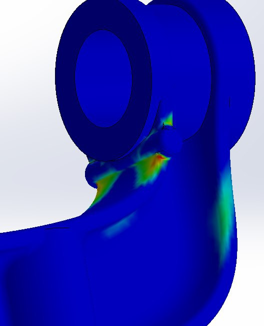
I started playing around with some FEA analysis to just see what I need to change in the model to make it suitable. The results below mean absolutely nothing in a practical sense as I was using a fictional material and fictional forces, but when I'm done with the arms I'll generate a report like below. It will tell me about the structural limits of the parts, including properties like flex. The second image is the more interesting one. I suspected that the two bosses near the bushing points were in fact included intentionally as strain relief. FEA shows that the strain focus is at that joint and so those bosses were put there on purpose. I wonder if older arms didn't have that boss and were susceptible to cracking, or if they worked it out before putting any of it out for manufacture?

68525
68526
 

lambertius

Banned
Messages
341
Hello comrades!

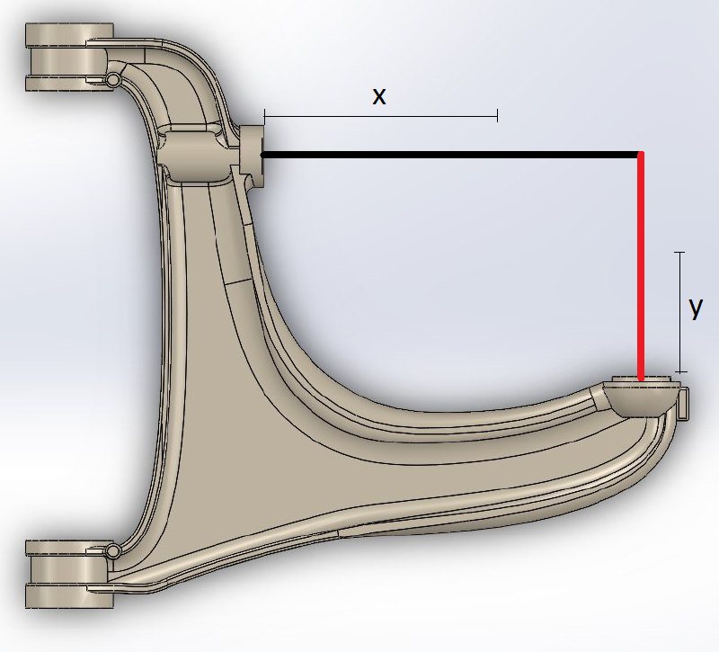
Would someone be able to help me out? I need to know the distances to the mounting points to the shock and the hub. I've marked out what I'm asking for on the below image. It will be a few weeks before I have access to my car again, so if someone could kindly provide those details it would allow me to continue along my merry way.

68615
 

Paulrv2

Junior Member
Messages
87
My replacement front and rear lower control arms and front upper ball joints arrived today and will hopefully be fitted to the car next week. I can measure the marked distances in your drawing before I deliver them to guys doing work for me if that would help?
 

lambertius

Banned
Messages
341
X is variable...

Resting position is good enough. Analysing suspension dynamics is a pita and not fully necessary for what I'm doing. It is really only for setting up geometry for knowing the toe and camber changes through the swinging arc. For forces, it won't even change the result by a Nm.
 

Paulrv2

Junior Member
Messages
87
Just measured one of my new lower control arms and X=260 mm Y=150 mm give or take a couple of mm. That’s based on as delivered position of new track control arm so angle between XY coordinates not exactly 90 degrees