

boomerang
Member
- Messages
- 412
After gaining some experience in solving 3200GT CEL/limpmode problems, i would urge everyone to carefully check the Pedalpot in those cases!(Pedalpot=PP)
The SD2/3 tester would point out any problem with the PP of course, but not everyone has such a tester lying around i'm afraid.
In most cases, they are worn or dirty inside at about the same time the TB starts making trouble.
The PP can be opened, modified and cleaned inside.
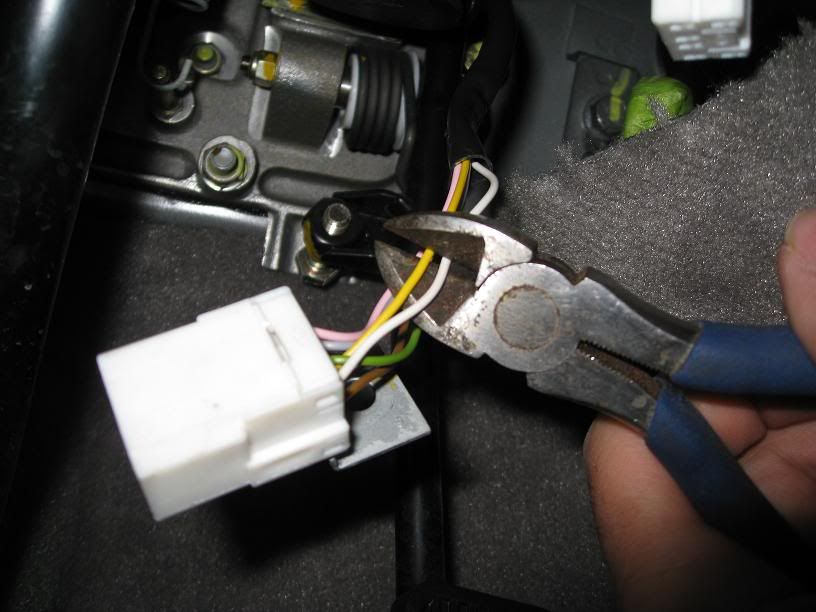
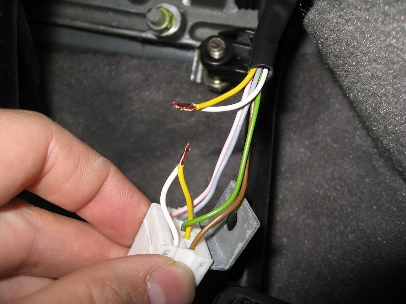
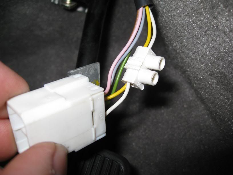
The last thing to do, is to delete the connector at the PP and solder each wire instead, isolating every wire afterwards of course.
Bad connections/ polution inside the PM can trigger CEL easily.
If someone was to send in a TB for overhaul/mod for contactless, you could concider sending the PP with it, if you would not trust yourselve with the mod./cleaning of the PP.
As you can see, the PP can be opened, the little round circuibourd can be deleted after removing the three dots of glue and after that, the resistortracks on it can be cleaned, as well as the little wiper. (Be very carefull not to harm the tiny wiper!) Use a greasy kind of contactspray.
Mark the position of the little board in its housing; it should be glued back in exactly the same position!
Then solder a bridge between the yellow and white wires inside the PP.
Close the PP and put it back in its place.
It would be wise to delete the connector and solder the wires afterwards as is said before.
Togeteher with a contactless TB, throttle problems will be history after this.
Here is a link with some pics of the internals of the PP:
========================================================================
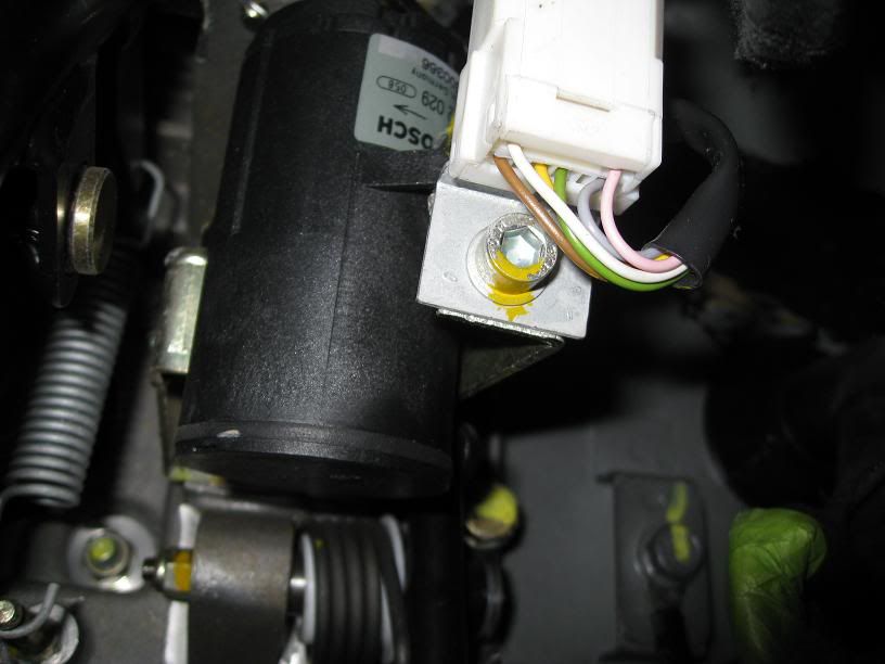
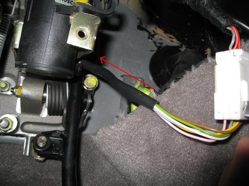
Because of the occasional check engine, i checked the PP this weekend.
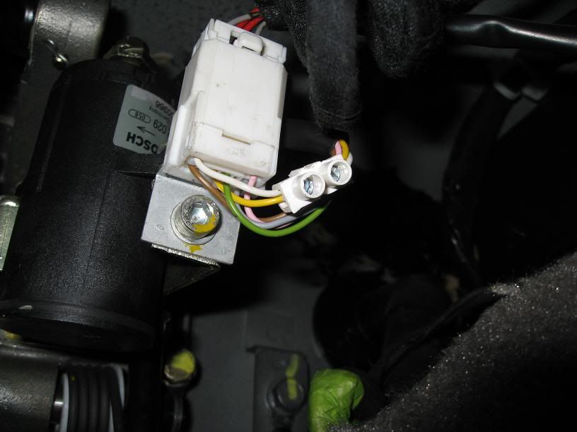
The potmeterunit (Bosch) has two internal potentiometers.
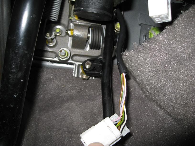
After disassembly - it sits on a hernia place - remove the unit from the linkage to the ball joint. Make no adjustment to the linkage between the pedal and unit !!
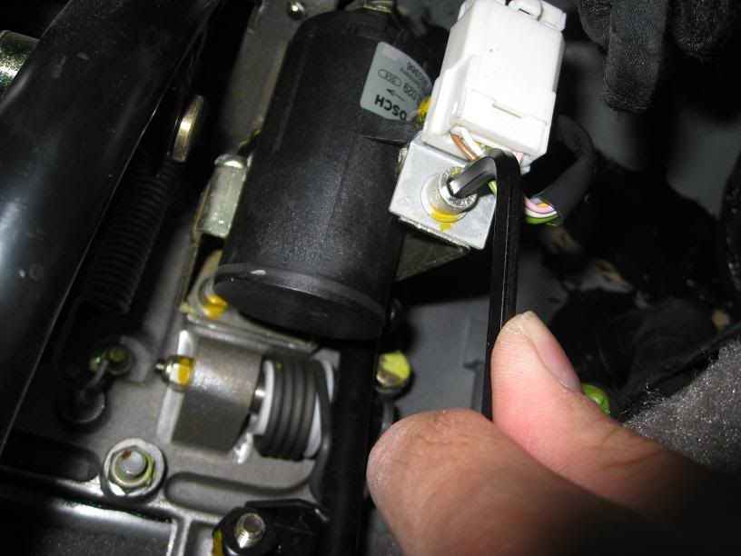
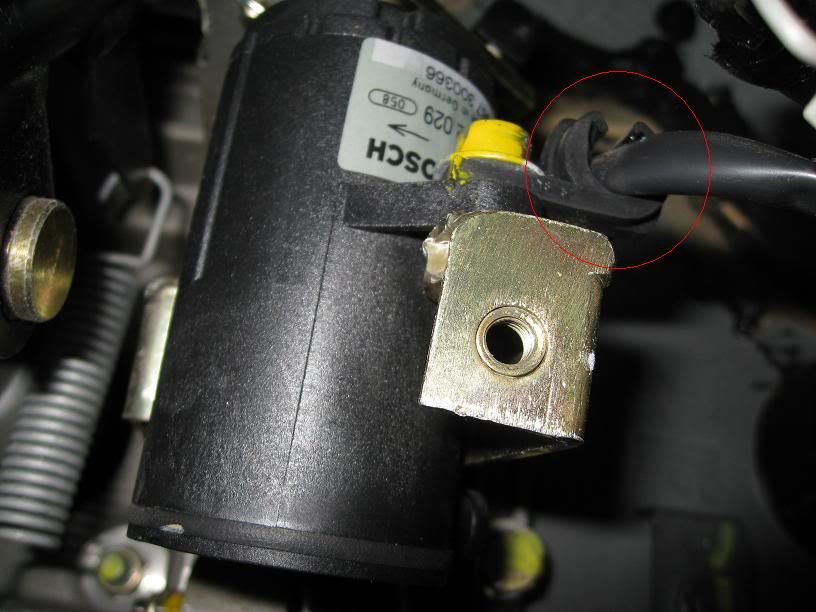
Now carefully remove the lid: (Careful with the plastic latches)

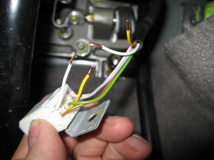
You will see the back of the potentiometerboard.

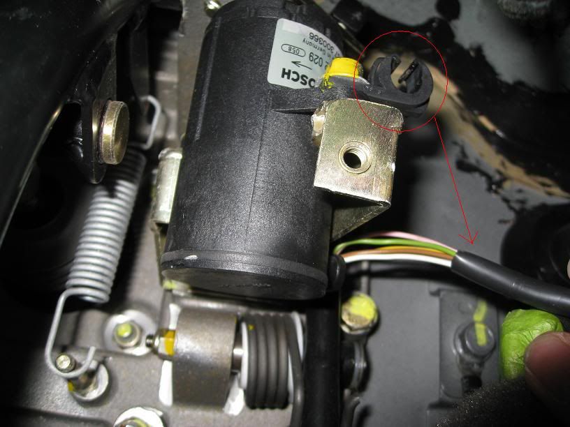
Now, with the wires deleted, you can see the 3 drops of rubberglue.(One deleted allready at the opposite side of the existing two)
Mark the position of the resistorboard in its housing, delete the glue and try to delete the board from its housing.

The resistorboard deleted from its housing with a little screwdriver.
Again, be carefull not todamage anything!
Now showing the little wiper that has to be cleaned with pressed air or a tiny brush, but again be very careful!

The resistortracks where somewhat dirty because of some debrees; just remove the dirt and apply some greasy contactcleaner.
If the resistortracks look really worn/scratched, please do yourselve a favour and order a new PP!

When you did NOT mark the position of the resistorboard in its housing properly, read this:
The ECU will open the ETM for idle when the PP sends a signal between 350mV and 600mV.
Max throttle will be applied at 2900-3700mV from the PP.
By gently rotating the board in its housing, you can achieve these values at idle, then bond the board to its housing again with three dots of glue.
If you did not mark the position of the board in its housing, you will have to measure these values, or nothing will go at all anymore!
Marcel had a setup created with 5V 100mA max power supply, + between pink and - at the brown wire (of the potentiometer unit), then measure between white and brown.

If you dó have to calibrate, try to achieve a 450mV reading.
Carefully turn the potentiometer shaft to max and then measure again; should be about 3400mV.
Check these values for potentiometer2, so 5V between + green and gray - and measured from yellow. If everything is ok, you should be "in range" here as well.
End of Dutch link.
=======================================================================
After this, apply the dots of glue and solder the new connection between the white and yellow "reading wires"".
Now there can never occur different readings from the two potentiometers again, causing the ECU to go in limp mode!
A well known Dutch Maserati specialist told me this modification was applied by Maserati all so later on!
Can some UK specialist confirm this, just curious?
Put everything back on its place again, delete the connector and directly solder the regarding wires to eachother.
After this AND a proper TB mounted, you should be freed from throttle problems.
DONT FORGET TO DO THE TROTTLE RESET PROCEDURE AFTERWARDS!!
Hope this is of some importance to you guys!
The SD2/3 tester would point out any problem with the PP of course, but not everyone has such a tester lying around i'm afraid.
In most cases, they are worn or dirty inside at about the same time the TB starts making trouble.
The PP can be opened, modified and cleaned inside.
The last thing to do, is to delete the connector at the PP and solder each wire instead, isolating every wire afterwards of course.
Bad connections/ polution inside the PM can trigger CEL easily.
If someone was to send in a TB for overhaul/mod for contactless, you could concider sending the PP with it, if you would not trust yourselve with the mod./cleaning of the PP.
As you can see, the PP can be opened, the little round circuibourd can be deleted after removing the three dots of glue and after that, the resistortracks on it can be cleaned, as well as the little wiper. (Be very carefull not to harm the tiny wiper!) Use a greasy kind of contactspray.
Mark the position of the little board in its housing; it should be glued back in exactly the same position!
Then solder a bridge between the yellow and white wires inside the PP.
Close the PP and put it back in its place.
It would be wise to delete the connector and solder the wires afterwards as is said before.
Togeteher with a contactless TB, throttle problems will be history after this.
Here is a link with some pics of the internals of the PP:
========================================================================
Because of the occasional check engine, i checked the PP this weekend.
The potmeterunit (Bosch) has two internal potentiometers.
After disassembly - it sits on a hernia place - remove the unit from the linkage to the ball joint. Make no adjustment to the linkage between the pedal and unit !!
Now carefully remove the lid: (Careful with the plastic latches)
You will see the back of the potentiometerboard.
Now, with the wires deleted, you can see the 3 drops of rubberglue.(One deleted allready at the opposite side of the existing two)
Mark the position of the resistorboard in its housing, delete the glue and try to delete the board from its housing.
The resistorboard deleted from its housing with a little screwdriver.
Again, be carefull not todamage anything!
Now showing the little wiper that has to be cleaned with pressed air or a tiny brush, but again be very careful!
The resistortracks where somewhat dirty because of some debrees; just remove the dirt and apply some greasy contactcleaner.
If the resistortracks look really worn/scratched, please do yourselve a favour and order a new PP!
When you did NOT mark the position of the resistorboard in its housing properly, read this:
The ECU will open the ETM for idle when the PP sends a signal between 350mV and 600mV.
Max throttle will be applied at 2900-3700mV from the PP.
By gently rotating the board in its housing, you can achieve these values at idle, then bond the board to its housing again with three dots of glue.
If you did not mark the position of the board in its housing, you will have to measure these values, or nothing will go at all anymore!
Marcel had a setup created with 5V 100mA max power supply, + between pink and - at the brown wire (of the potentiometer unit), then measure between white and brown.
If you dó have to calibrate, try to achieve a 450mV reading.
Carefully turn the potentiometer shaft to max and then measure again; should be about 3400mV.
Check these values for potentiometer2, so 5V between + green and gray - and measured from yellow. If everything is ok, you should be "in range" here as well.
End of Dutch link.
=======================================================================
After this, apply the dots of glue and solder the new connection between the white and yellow "reading wires"".
Now there can never occur different readings from the two potentiometers again, causing the ECU to go in limp mode!
A well known Dutch Maserati specialist told me this modification was applied by Maserati all so later on!
Can some UK specialist confirm this, just curious?
Put everything back on its place again, delete the connector and directly solder the regarding wires to eachother.
After this AND a proper TB mounted, you should be freed from throttle problems.
DONT FORGET TO DO THE TROTTLE RESET PROCEDURE AFTERWARDS!!
Hope this is of some importance to you guys!
Last edited: