Inlet manifold removal on a QP V

B16 ONX

Junior Member
Messages
95
Hey guys
So since I bought my QP back in March it has never been "right". The power delivery wasn't as smooth as I expected, the clutch control was terrible when it was cold, the throttle had very little connection with the engine when it was cold & it wouldn't rev past 5500 rpm. When it was hot it was better, but only better not right. It felt like it was down on power, not by much but didn't have that "vigour" I was expecting.

As this was my first QP V I reluctantly put it down to being how it was supposed to be.....but then common sense kicked in & there is no way Maserati would release a car with these characteristics.

I took it to Vince@ Migliore Cars for him to give it a once over & he agreed with the lack of revs but felt all else was ok.

He carried out a free diagnostic check which found that the knock sensor was faulty. He cleared the fault & we left it at that. Last month I had enough so I contacted him again so he could get to the bottom of the fault as it was no longer any fun.

Unfortunately he was going away on holiday the following week & would be busy before & after his holiday so I reluctantly booked it in at Graypaul in Solihull.

They had it for a couple of days & they came back with the same diagnosis, the knock sensor was faulty. I asked how much to remove & replace & was quoted £1478 for parts & labour!

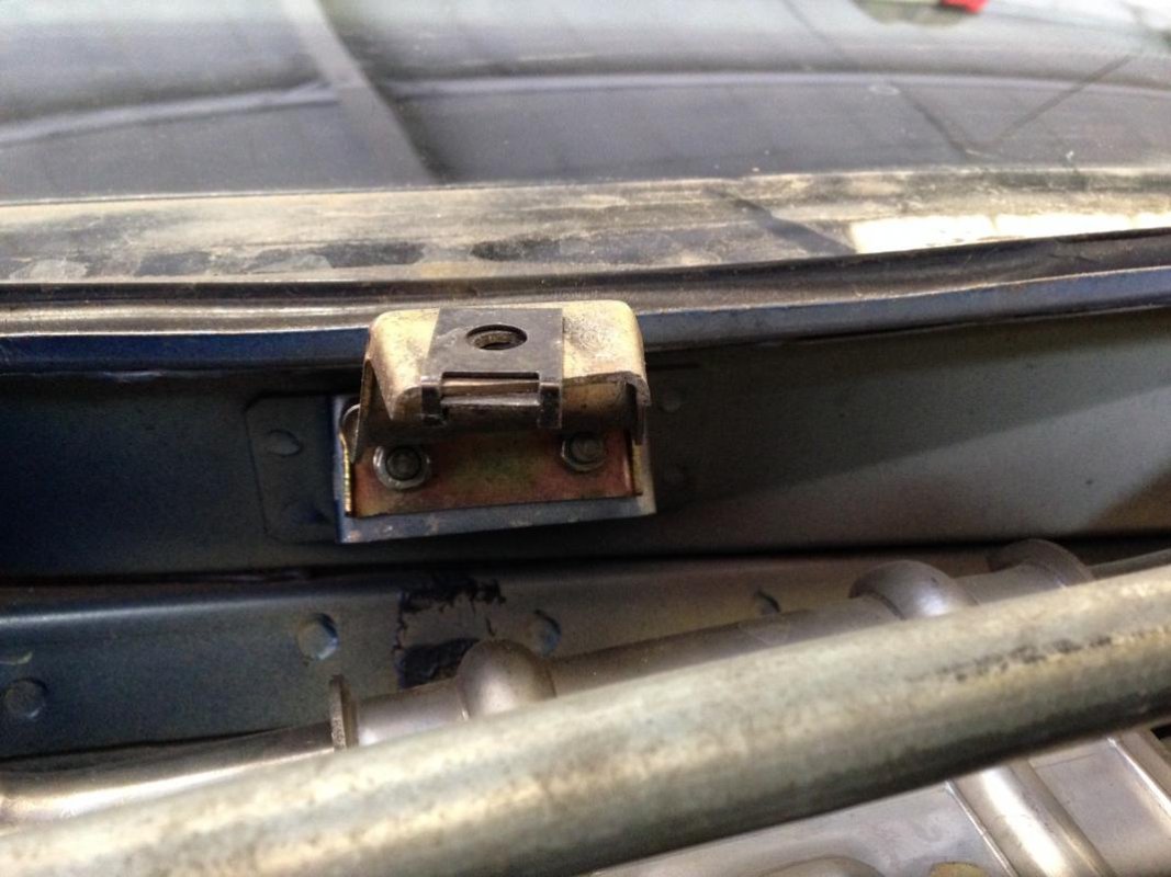
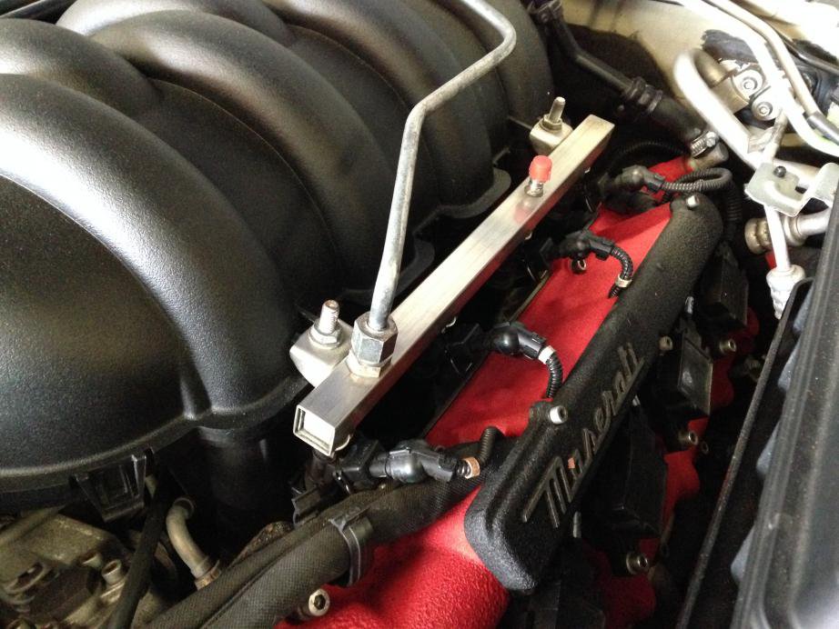
I brought the car back whilst I pondered what to do. I decided to do the job myself, how hard could it be?

This is how hard it was......
 

B16 ONX

Junior Member
Messages
95
First job was to remove the three engine covers/panels.
I wanted to see what was behind them & I wanted as much space to work in.IMG_1266.jpg
 

RSM Masser

Member
Messages
2,437
I await with baited breath - done the knock sensors change on a 3200 last year - not too difficult, very fiddly and time consuming, just who thought of putting the longest bolt on the starter motor that refused to accept more than 1/16 of a turn despite a variety of odd shaped spanners including 'get out jail free' half moon ratchets
 

B16 ONX

Junior Member
Messages
95
IMG_1268.jpgIMG_1268.jpgThe panels were held in by T25 screws & 2x cross heads. They all lifted out to reveal the full engine bay. At this stage I put my wing cover on for protection
 

B16 ONX

Junior Member
Messages
95
**** this is taking much longer than I thought! I will finish after work as I am sure someone will notice me not working!!
 

conaero

Forum Owner
Messages
34,652
Keep going, its not very difficult to do, from memory:

  1. Remove engine covers
  2. Disconnect battery
  3. Disconnect throttle body
  4. Remove fuel rail fixings
  5. Remove injectors (carfully)
  6. Undo the various pipes attached to the plenum
  7. Undo the 16 screws holding the unit on the heads
  8. Lift up and away
  9. BLOCK THE INLET HOLES TO THE ENGINE WITH RAG


Refitting is the reversal of the removal.
 

drewf

Member
Messages
7,159
Keep going, its not very difficult to do, from memory:

  1. Remove engine covers
  2. Disconnect battery
  3. Disconnect throttle body
  4. Remove fuel rail fixings
  5. Remove injectors (carfully)
  6. Undo the various pipes attached to the plenum
  7. Undo the 16 screws holding the unit on the heads
  8. Lift up and away
  9. BLOCK THE INLET HOLES TO THE ENGINE WITH RAG


Refitting is the reversal of the removal.

I think he means uploading the photos etc Matt...
 

Klive

Junior Member
Messages
724
Keep going, its not very difficult to do, from memory:

  1. Remove engine covers
  2. Disconnect battery
  3. Disconnect throttle body
  4. Remove fuel rail fixings
  5. Remove injectors (carfully)
  6. Undo the various pipes attached to the plenum
  7. Undo the 16 screws holding the unit on the heads
  8. Lift up and away
  9. BLOCK THE INLET HOLES TO THE ENGINE WITH RAG


Refitting is the reversal of the removal.

Then, if it's the same as the Coupe, you need to remove the Oil Pressure Switch to take out the knock sensor. In which case, change the OP switch while you're there.
 

drewf

Member
Messages
7,159
Have you resized them before uploading? There's no point in uploading mega resolution photos...
 

B16 ONX

Junior Member
Messages
95
With the trims out I removed the wiper motor & rear trim.
The wiper arms were held in with with a 17mm nut. the motor was 3x 10mm.
The wiper motor wiring was connected below the motor.
Then gently tweek the bracket up to pull the motor out.
The back panel was screwed in place.
Release 2 bolts holding the brake fluid reservoir then pull the rear panel out.

With these out of the way you can access the back of the engine.
 

Attachments

  • IMG_1270.jpg
    IMG_1270.jpg
    91.6 KB · Views: 15
  • IMG_1271.jpg
    IMG_1271.jpg
    88.5 KB · Views: 16
  • IMG_1272.jpg
    IMG_1272.jpg
    96.2 KB · Views: 18

drewf

Member
Messages
7,159
If you use Outlook or similar, a quick way is to attach them to an email, then save the attached images, as Outlook will automatically reduce them to a very useful size.

Alternatively, use a free photo editor (Paint.net is pretty good) to change the image size - easy via the menus. Try making them 800x600 and saving as 90% quality jpgs. I'm assuming you are using a Windows PC...
 

drewf

Member
Messages
7,159
You don't actually send the email btw, just select the attached images and save them!
 

B16 ONX

Junior Member
Messages
95
With the rear panel out of the way the manifold was easy to access.

I was dreading this as I thought it would held in with some awkward nuts & bolts assembly!

I blew over the manifold joint with an air line to remove any dirt & debris.

Then removed the fuel line & breather hose on the nearside.
 

Attachments

  • IMG_1275.jpg
    IMG_1275.jpg
    92.9 KB · Views: 21
  • IMG_1276.jpg
    IMG_1276.jpg
    94.5 KB · Views: 20

B16 ONX

Junior Member
Messages
95
With the near side fuel line & breather hose undone I looked at the off side.

That was the side that gave me a little bother initially but a minute of looking at it & it was simple.

Release the breather hose then the vacuum & fuel lines. The vac hose t's off to a smaller hose that goes behind the throttle body & into the intake hose at the front. This hose is rigid so I avoided bending it too much by removing the intake hose/air flow meter first. Mind the metal bracket in front of the manifold holding a hose out of the way. I just gently pulled it out of the way.
IMG_1277.jpgIMG_1278.jpgIMG_1279.jpg
 

B16 ONX

Junior Member
Messages
95
With the breather, vacuum & fuel lines out of the way I was clear to undo & remove the inlet manifold.
I blew over the bolts securing it with the air line again, just to make sure it was clean.

I then released the bolts holding it in place, 16x 5mm allen head bolts. I tapped the extension bar with a plastic hammer to make sure the tool was in place secure.

I then lifted it out of the way to find 2 small vacuum hose underneath, so I pulled them both off & removed the manifold.

IMG_1282.jpgIMG_1284.jpg
 

B16 ONX

Junior Member
Messages
95
With the manifold out of the way I could see the knock sensors & a good view into my engine.

The knock sensors were covered in dust & dirt as I expected....then I saw some fur......

IMG_1286.jpgIMG_1287.jpgIMG_1289.jpg
 

B16 ONX

Junior Member
Messages
95
The knock sensor had been eaten by a rodent of some description. The more I looked the more I found of him!

I removed the pressure chamber from the middle so I could vac all the debris out.

I then replaced the 4 knock sensors one at a time with the new ones I bought. 1 was eaten through, 1 was eaten on the outer coating only, the remaining 2 were okay. I didn't know what I was expecting to find when I started the job so I ordered all 4 knock sensors on the basis if 1 failed then the other 3 can't be too far behind.

I am glad I had all 4 to hand now, having found out what the problem was!IMG_1295.jpgIMG_1296.jpgIMG_1298.jpgIMG_1300.jpg