Does anyone have......

Andy Marshall

Member
Messages
297
a set of installation instructions for the switchable Larini exhausts? I have the full kit with the key fobs etc that was removed from another GT. Obviously the silencers are the easy bit, and I do have the twin vacuum feeds for my current OEM silencers (its a 4.7S) but I'd love to fit the override bits.
I am told it's not THAT difficult!
 

Andy Marshall

Member
Messages
297
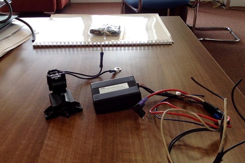
well, aside from two very pretty Larini back boxes (obviously! ) I got some rubber hose, a black thing that looks like it has two vacuum pipe connections (arranged in an L shape at one end) with a two wire connector on the other end of it. The two wires are both black. One has a "eye" on it (as if connected to a stud) and the other was connected to a grey wire (its been cut at the grey wire connector) The grey wire appears identical to the grey wire on the small black box below.

The small black box, which I think is the control unit for the bluetooth fobs, ( I got two fobs) has 5 wires coming out of it - a thick red with what appears to be a piggy back fuse connector (3 amp fuse present) labelled 12v in, the aforementioned grey wire labelled 12v out, a blue wire labelled Ant. and two black wires, one of which is labelled GND and the other has no label.
The grey wire and the two black wires are sort of taped into a bunch of 3 as if they went to the same (ish) place

Thats it. Any clues?
 

azapa

Member
Messages
1,300
a picture of the bits and pieces wouldn't do any harm! as Catman says: should be really easy to install. Have you tried asking FD for a copy of the instructions? regarding the vacuum solenoid valve, that may have a flow direction, in which case little arrows will be indicated on the plastic body. Flow is towards the engine, in the case of vacuum!
 

CatmanV2

Member
Messages
48,796
well, aside from two very pretty Larini back boxes (obviously! ) I got some rubber hose, a black thing that looks like it has two vacuum pipe connections (arranged in an L shape at one end) with a two wire connector on the other end of it. The two wires are both black. One has a "eye" on it (as if connected to a stud) and the other was connected to a grey wire (its been cut at the grey wire connector) The grey wire appears identical to the grey wire on the small black box below.

The small black box, which I think is the control unit for the bluetooth fobs, ( I got two fobs) has 5 wires coming out of it - a thick red with what appears to be a piggy back fuse connector (3 amp fuse present) labelled 12v in, the aforementioned grey wire labelled 12v out, a blue wire labelled Ant. and two black wires, one of which is labelled GND and the other has no label.
The grey wire and the two black wires are sort of taped into a bunch of 3 as if they went to the same (ish) place

Thats it. Any clues?

Yes, but some photos will help....
The black thing is the solenoid valve. So you need a vacuum hose plugged in with a t-piece to your existing bottle, then to the exhaust actuators. The wire with the eye is probably the earth, the other will connect to the black box as you surmised.
Black box:
The red wire is the 12v feed. Piggy back to the fusebox under the bonnet
Grey is the output voltage
Blue is the antenna. Try to keep it straightish and away from metal
GND is the earth
The other black one is probably to provide an earth for the solenoid. On my kit they were effectively shorted I believe

So you should be good :)

No seriously, I think we can talk you through this if it's not enough.

C
 

Andy Marshall

Member
Messages
297
Photo on 31-05-2017 at 14.47.jpg

So here is a picture of what I have. I have been in touch with Larini and they are sending me a wiring diagram, but the issue now is how to do the vacuum bit. At present the exhausts use vacuum to stay closed until the sports mode is engaged. I want to keep that PLUS add in the selectability of the remote Larini unit.
So my thinking is to T in the Larini solenoid between the OEM Maserati solenoid and the rear silencers and have it sucking against the closed position of the Larini solenoid (which I think is the horizontal pipe connection ) . That way, the exhausts stay closed as the suction will still go to the silencers to close the valves. Then when I open the Larini Solenoid the oem solenoid will draw air through the Larini unit instead of being able to pull the vacuum and thus the rear valves will open. Does this sound logical? Am I making a problem for myself?
 

Andy Marshall

Member
Messages
297
OK, I think he did what I am proposing, which is good! One question though, what do I do with the "open" side of the new solenoid (i.e., the bit through which air is drawn when open? ) In Namaste's picture there is a pipe connected to both solenoid inputs - do I just put a length of open pipe on the open side and hide it somewhere clean so that water/**** doesn't get in?
 

azapa

Member
Messages
1,300
I may need a coffee yet, but there will be NO open end. All this does is let the vacuum arrive from the standard set up (when OFF) or stop the vacuum arriving from the standard set up (when ON). I am assuming here that your car already has valves and the standard "sport" set up to open them. The valve you show just goes in line with the original one.

I'll make some coffee, and read again after posting, and edit duly if needed...
 

namaste

Member
Messages
212
OK, I think he did what I am proposing, which is good! One question though, what do I do with the "open" side of the new solenoid (i.e., the bit through which air is drawn when open? ) In Namaste's picture there is a pipe connected to both solenoid inputs - do I just put a length of open pipe on the open side and hide it somewhere clean so that water/**** doesn't get in?

Hi Andy

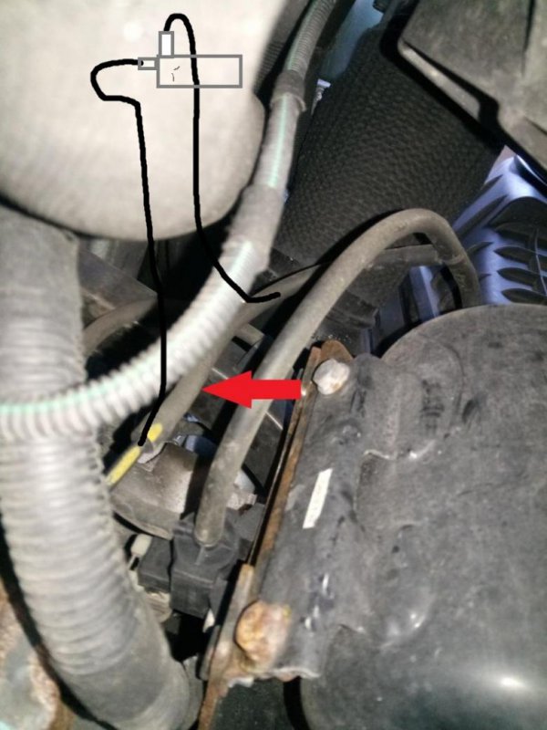
The vacuum passes through the solenoid. I've included a highly technical illustration below. The red arrow is pointing to the pipe you want your new solenoid to be placed inline with. You put the pipe from the T-piece to one solenoid input, then attach another piece of pipe from the solenoid output to the solid vacuum pipe that travels to the rear tailpipes. Bearing in mind that this mod of mine uses a standard 12v/0v on/off solenoid. Your kit uses an original Maserati solenoid I believe which is designed for use where no solenoid exists (as was the case in Catman's install). I should think it'll still work but its simple to find out and put back to standard if not.

Also, you've got a mini piggy back fuse holder which is good. I've got one on order and will be piggy backing off one of the mini fuses at the front of the fuse box that get 12v with ignition on. I bought the standard fuse size piggy back and the only fuse I could get on was the air-con, which isn't ideal because it means the mod only works with the air-con on! I've edited my original thread to mention this.

pic74565.jpg
 

Andy Marshall

Member
Messages
297
AHA! Ok, I think I get it. Thanks all. I'll keep you all posted as to progress. Hope to get to this at the weekend!
 

namaste

Member
Messages
212
AHA! Ok, I think I get it. Thanks all. I'll keep you all posted as to progress. Hope to get to this at the weekend!

Good luck. Its a little cramped under there, just make sure you've got some decent stands so that 2 ton lump doesn't fall on your head!
 

CatmanV2

Member
Messages
48,796
Well done :) It's a closed system. Imagine the bottle is storing vacuum, and you're simply connecting the valves to the bottle. There can't be an open end :)

C
 

CatmanV2

Member
Messages
48,796
Something's been nagging me about this. I just remembered, that solenoid in the picture drives the secondary air valves. The exhaust control solenoid is at the back. Makes no difference in this application. Your new solenoid will work the same way. Open is and the sports button will have override. Close and and your exhaust will be load.

C
 

Andy Marshall

Member
Messages
297
Well I have completed wiring in the electrical bits, and the good news is that that bit appears to work (cycling the remote produces the right results on the pneumatic solenoid thingy) For reasons I can't be arsed to go into I have had to mount the solenoid up near the fuse box. From here I have run two rubber hoses across the front engine bay cross member, ready to intercept the vacuum line which from the pictures on here appears to be somewhere on the drivers side , under the under tray. I just need to get some 3mm connectors to complete the task.
One last question though - is there really no where in the engine bay where I can intercept the vacuum line, thereby removing the need to take off the under tray?
 

namaste

Member
Messages
212
Well I have completed wiring in the electrical bits, and the good news is that that bit appears to work (cycling the remote produces the right results on the pneumatic solenoid thingy) For reasons I can't be arsed to go into I have had to mount the solenoid up near the fuse box. From here I have run two rubber hoses across the front engine bay cross member, ready to intercept the vacuum line which from the pictures on here appears to be somewhere on the drivers side , under the under tray. I just need to get some 3mm connectors to complete the task.
One last question though - is there really no where in the engine bay where I can intercept the vacuum line, thereby removing the need to take off the under tray?

Sure, just take the radiator out! You're almost there though. :goodjob:
 

CatmanV2

Member
Messages
48,796
I moved the flexible connectors on the air box. I could then reach from the top. Quite simple really

C