You are using an out of date browser. It may not display this or other websites correctly.
You should upgrade or use an alternative browser.
You should upgrade or use an alternative browser.
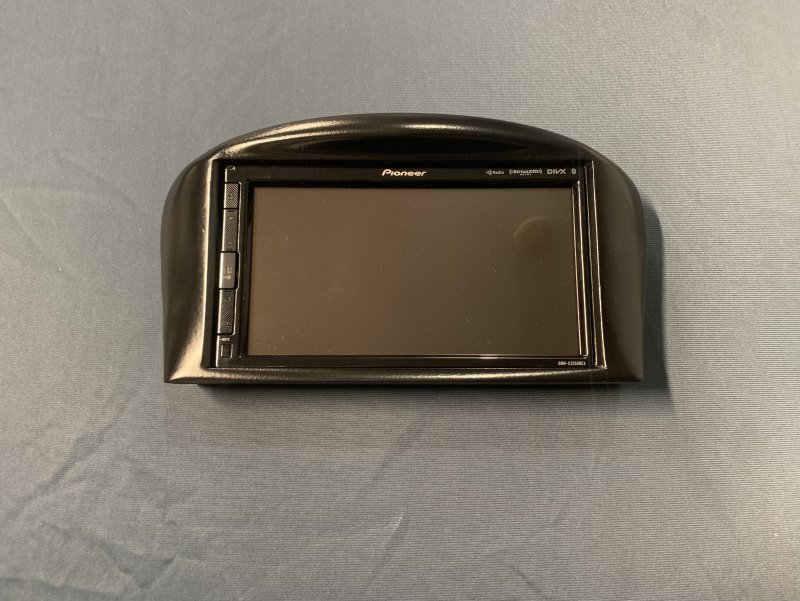
New 2DIN radio receiver bezel for Maserati 4200 Coupe/Spider
- Thread starter k1coupe
- Start date
k1coupe
Junior Member
- Messages
- 99
Enclosed Pioneer installation manual page 4 describes how to wire to external power amp(Pioneer's), weather you could do without
Pioneer power amp and substitute it with your factory amp or not, I think you should, you could try it. It should not pop as what you wire into power amp differs from direct wires to speakers( it's the pre amp signals rather than going to internal head unit amp now you fed into external power amp).
Pioneer power amp and substitute it with your factory amp or not, I think you should, you could try it. It should not pop as what you wire into power amp differs from direct wires to speakers( it's the pre amp signals rather than going to internal head unit amp now you fed into external power amp).
Attachments
Last edited:
k1coupe
Junior Member
- Messages
- 99
For 3D printing material it is best you consult the shop you print and tell them what you want, obviously you want hard plastic but also
tell them the color, shiny or matte and let the shop tell you which one of their material works best for you. The shop that printed
for me charged $16 extra smoothing the surface for me( otherwise you end up sanding), some other shops quoted that they deliver
very smooth shiny black plastic( their prices were too high), for the 30% smaller than mine radio bezel you are printing, I expect $80
to $100 price.
Not familiar with plastics, I was confused to see so many different types on websites specially that some of them are rubber like and some are just for a visual modeling and may crumble holding something in place.
As for the power amp and subwoofer, I have none, my JVC receiver drives the 4 speakers directly.
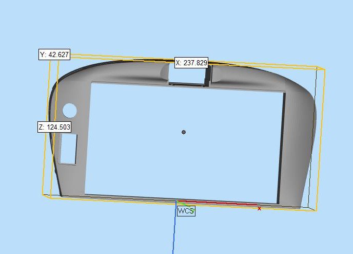
On 2/3/21 I am done with fixing the bezel for Pioneer and radio receivers 60mm or less deep, this bezel mounts FLUSH with surrounding leather, so those who are crazed about flush mount can enjoy it too and buy themself Pioneer or else:
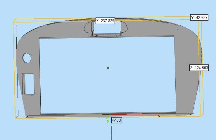
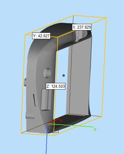
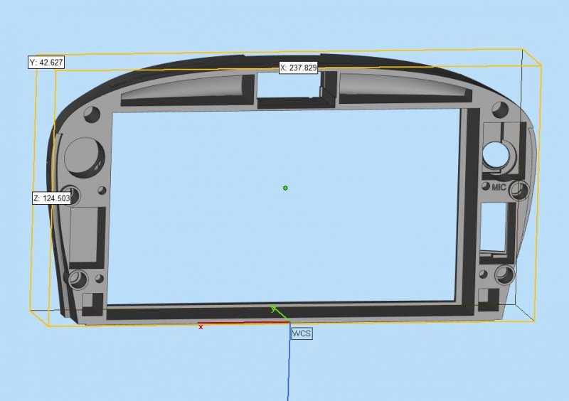
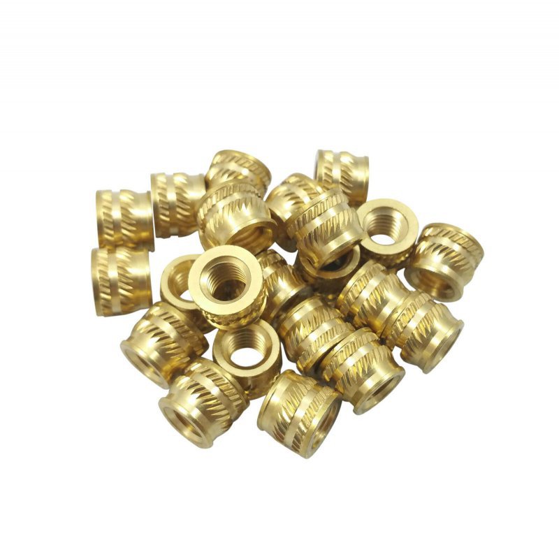
The 4 mounting holes are adjusted to take in 5mm brass inserts:
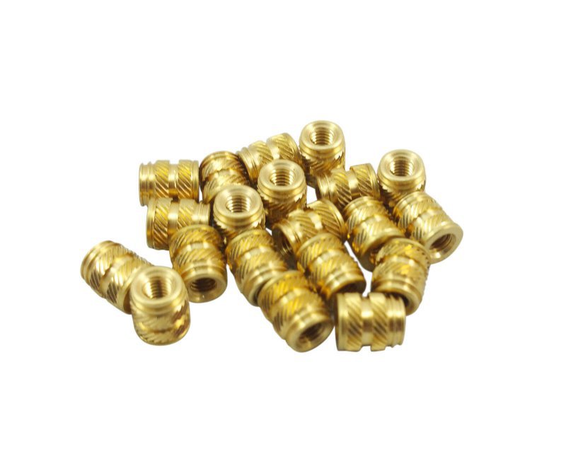
4 smaller holes are for 3mm brass inserts:
tell them the color, shiny or matte and let the shop tell you which one of their material works best for you. The shop that printed
for me charged $16 extra smoothing the surface for me( otherwise you end up sanding), some other shops quoted that they deliver
very smooth shiny black plastic( their prices were too high), for the 30% smaller than mine radio bezel you are printing, I expect $80
to $100 price.
Not familiar with plastics, I was confused to see so many different types on websites specially that some of them are rubber like and some are just for a visual modeling and may crumble holding something in place.
As for the power amp and subwoofer, I have none, my JVC receiver drives the 4 speakers directly.
On 2/3/21 I am done with fixing the bezel for Pioneer and radio receivers 60mm or less deep, this bezel mounts FLUSH with surrounding leather, so those who are crazed about flush mount can enjoy it too and buy themself Pioneer or else:


The 4 mounting holes are adjusted to take in 5mm brass inserts:

4 smaller holes are for 3mm brass inserts:

Attachments
Last edited:
k1coupe
Junior Member
- Messages
- 99
The zip file you sent to your local guy has 2 bezels , bezel3 and bezel 4, bezel4 does not have a hole for microphone.The connectors are 3,I just saw the you did this! Thank you much, I am sending your file to a local to me guy and see what he comes up with. On another note, and sorry if someone already posted it, but what connectors would I need to get so I don't have to cut my wires?
the 6pin white is available from Allied Electronics in USA, the other 2 eight pin connectors are not for sale in USA but sell on Aliexpress.com
with a month for shipping it from Singapore. Let me know if you need the part numbers for the connectors and their pins (6 items) and
you want to order them.
On the other hand I bought them in December and got my 10 packs, used one only, so if you are in USA I could send you 3 connectors,
20 pins an 8 brass inserts at near cost plus shipping.
k1coupe
Junior Member
- Messages
- 99
and I am in Niagara zip 14305 so no rush, wait till you get your bezel, look at shapeways.com too, it is very close tou you, do not pay over $150 for that bezel no matter what the material or post processing (paint etc) be (i.materialise price is $116 Polyamide(MFJ) black dye and $160 polyamide(SLS) black dye, no need to go more expensive SLS process).
The part numbers are:
6pin white mating connector(old display) 1-174930-1, pins are 173336-1
mating connectors for NIT 8pins at Aliexpress:
Tyco 3.5mm 8 Pin Male Female Brown Black Middle Slot Auto ISO Radio Horn CD Plug Connector for Car Toyota Lexus VW
Hazard switch is on ebay and Amazon: Mitsubishi Pajero ShogunHazard Warning Light Switch
I have them all and from Niagara To Suffolk takes only 2 days in mail but you could buy yourself too
you may want to download an stl file viewer so you see the items on your computer screen:
Materialise MiniMagics | Your free file viewer
k1coupe
Junior Member
- Messages
- 99
Good news, let me know if you got bezel with hole for Microphone or you ordered your bezel with no hole for microphone.
Now since you are getting Pioneer only need to run 2 cables from where you put the Pioneer receiver to the front
that you install your bezel and Pioneer display, the cables will be the Pioneer graphic display cable that you'll be buying from
Pioneer and the panel mount USB cable.
If you are taking out the NIT and place your Pioneer receiver there all you need is 2 connectors plus 17 pins to mate Pioneer receiver pigtails to 2 cables that were plugging into NIT, then you are not cutting anything from your car harness.
You also need a 6pin connector to wire it to hazard switch and plug it into white 6pin connector that was plugged int NIT display.
So we are talking about 3 connectors, 23pins, the hazard switch and panel mount USB cable. I have them all except one connector
That I ordered some time ago and it's coming any day.
There is also a matter of AC dials back lights below the display that are turned on be applying a reference voltage to Yellow/black
wire of the 6pin connector, others been buying a step down regulator (about $10) and wire it to car 12V and connecting it to Y/b
wire, I might have an easier solution that can reduce the wiring and incorporate that into harness that connect the hazard switch
to the 6pin white connector.
Let me know when you receive your Pioneer and I try to get you the other parts by then, and post a photo of your bezel if you could.
I also have the 8 brass inserts that you will be pushing into your bezel. 4 ball head locating pins needed to mount the bezel into dash
are hard to find I unscrew them from my NIT display to re use on the new bezel , you will end up doing that too, they go into four
5mm brass inserts.
Last edited:
Masera
Member
- Messages
- 144
For now, I went with the original bezel design with no cut outs. Reason I did this is because I want to get everything working and then reevaluate what I want to change. The gentlemen that did my bezel lives 15 minutes from me and he only charged me $75 and told me he can work with me and/or others who may want any bezel made. I am in the process of finishing mine and will post pics once it is to my liking.
Do you want me to PM you my contact info?
Do you want me to PM you my contact info?
k1coupe
Junior Member
- Messages
- 99
OK , so all you need is 3 connectors and 4 brass inserts, 3 connectors and their pins are about $10 and brass inserts cost $2.
Pay $12 plus shipping after you receive them. on the original bezel you may need to enlarge the 4 holes for brass inserts about
0.5 mm before pushing the inserts into plastic.
For AC dials back lights use:
https://smile.amazon.com/dp/B00FPGL...us000-pcomp-feature-rscomp-wm-5&ref=aa_rscomp
but add a diode on the 7.5V output line to adjust voltage down a bit before connecting it to 6pin white connector Yellow/Black wire.
I send you a diode with the rest of stuff.
k1coupe
Junior Member
- Messages
- 99
You'll need these, maybe borrow them locally for a day:
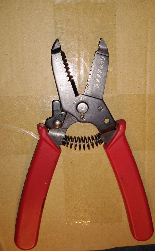
wire stripper
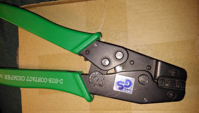
crimp tool
After crimping a pin to wire ends of your receiver pigtails, hold the pin and pull the wire to make sure connection is strong and will hold, also use a bug light or ohm meter to make sure electrical connection is good then insert the pins into connector heads.
when they are all the way in, you hear a click and the wire/pin stays in connector and not come out. Insert pins per below into
A and B:
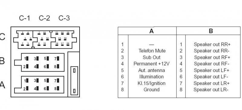
Note that there is a +12V spot for the pigtail yellow wire but there is no switched +12V in A or B, I connected that one to
a pin in 6pin white connector that has Switched +12V(will be long wire from NIT spot to front) and note that pins for
6pin white connector are different.
wire stripper

crimp tool

After crimping a pin to wire ends of your receiver pigtails, hold the pin and pull the wire to make sure connection is strong and will hold, also use a bug light or ohm meter to make sure electrical connection is good then insert the pins into connector heads.
when they are all the way in, you hear a click and the wire/pin stays in connector and not come out. Insert pins per below into
A and B:

Note that there is a +12V spot for the pigtail yellow wire but there is no switched +12V in A or B, I connected that one to
a pin in 6pin white connector that has Switched +12V(will be long wire from NIT spot to front) and note that pins for
6pin white connector are different.
Last edited:
Masera
Member
- Messages
- 144
I have been a little busy at work lately, but I did manage to touch up the bezel and paint it, it looks great! I will post some pics soon. I plan on tackling the install the majority of the install this weekend. One area that I think I still need some guidance on is wiring the step down transformer for the ac dial backlights that you recommended . Any additional input is appreciated! Once again, I can’t thank you enough!
k1coupe
Junior Member
- Messages
- 99
AC Dial backlights are turned ON when a voltage is applied to pin 6 (Yellow/black) wire of white connector that used to plug into the NIT display that you are taking out, possibly this voltage used to be generated and supplied by the NIT display that you are removing. I did not have time yet to find out why 7V and not more common 5V,6V,7.5V, 9V or 12V , so I supplied that line with the same 7V that others did and it works, the draw from the supplied voltage source seem to be less than 0.2 Amp (about 1.4 Watts). While 7V step down converters are uncommon,generating about 7V is easy and inexpensive and can be done by adding a diode on more common 7.5V step down converter, I used a 1N5401 diode, same as one I sent you. Wire(solder) the 7.5V output line of the 7.5V step down converter to one leg of diode and the other side of diode(marked with white line on black casing) to pin 6 of 6 pin white mating connector that I sent you and plug it in. You will be using 3 more pins of the 6 pin white connector, all together you crimp 4 pins on 4 wires and insert them into the white mating 6 pin connector shell. The other 3 wires are one for hazard switch(pin 1) that mates with grey/black wire (the other leg of hazard switch you just ground to the nearest metal on the car), Crimp a pin to Ground line of 7.5V step down converter and insert in pin 3 of the connector shell, the pin/wire you insert in pin 5 spot of connector shell(mating with car red wire) is the switched 12V and to be connected to 3 devices, 12V input of your step down 7.5V converter, also to your radio switched 12V and 3rd is the hazard switch light( again the other leg of hazard switch light just ground to the nearest metal on the car).
Last edited:
k1coupe
Junior Member
- Messages
- 99
Looks nice, now the hard part is to route the video cable under the center console from NIT cage to front, how did the brass inserts go into your bezel? generally when you place it on the hole and press gently in with a heated soldering iron it moves in, just make sure
you insert the correct side into plastic.
you insert the correct side into plastic.

