4200 Classico remote boot opening how to

CatmanV2

Member
Messages
48,736
OK, thanks for bearing with me. If any of you are interested in adding remote boot opening to your classic 4200 (with the black key) here's a way to do it that does not involve the quoter £1100 for a new alarm system :)
Couple of notes:
This is how *I* did it. I've been messing around with cars for 20+ years. I'm not a pro, I'm not an expert. I you don't like how I did it, don't do it my way :) Do it yours, and post another, better 'how to' :)
Scotchlock connectors. I've heard lots of people that seem to think these things are spawn of satan. Equally I've been using them for years and never *every* had one fail. I'd *probably not use them for a mission critical application, but if the connector in this fails the worst outcome could be inability to us the glovebox button, and maybe a blown fuse if the damaged wire connects to the chassis when the button was pressed, or the release activated. I think this is an acceptable risk, so I used a scotchlok. If you don't like them, use something else :)

Now on with the show!

First get your remote control. I opted for one of these:
http://www.ebay.co.uk/itm/150969772847?ssPageName=STRK:MEWNX:IT&_trksid=p3984.m1439.l2649

Seemed cheap enough, and the plib is pleasingly solid with a metal frame and a sliding cover over the buttons. Delivery was prompt to on to the instruction manual:
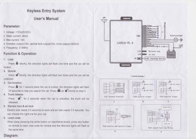
Scan.jpg

Not the greatest, but I've dealt with worse documentation from our development team :) From this I can see that it's pretty simple, and I know I need 12v to trigger the solenoid so I connected the positive feed (red) to the input (yellow and black) of the switched output (black and white) that I'd chosen to use, like this:
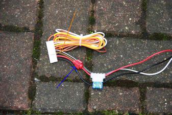
wiringloom.jpg

I've also shorted the yellow and black cable (arrowed in orange) and you can see the connector, arrowed in blue.

Now what do we do with it? You don't need to do this but, unless you want to ;)

The boot lid of a 4200 is lined. The lining is held on with plastic pins, arrowed in green:
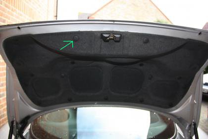
01bootlidliner01.jpg

I find the best way to get these off is a gentle pry with a flat bladed screwdriver to shift them, and then one of these:
http://www.ebay.co.uk/itm/ELECTRICA...t=UK_Hand_Tools_Equipment&hash=item2319336a8e

You can get the (blunt jaws) under the head, and then lever without much fear of damaging anything. So all clips removed and the lining comes off to reveal:
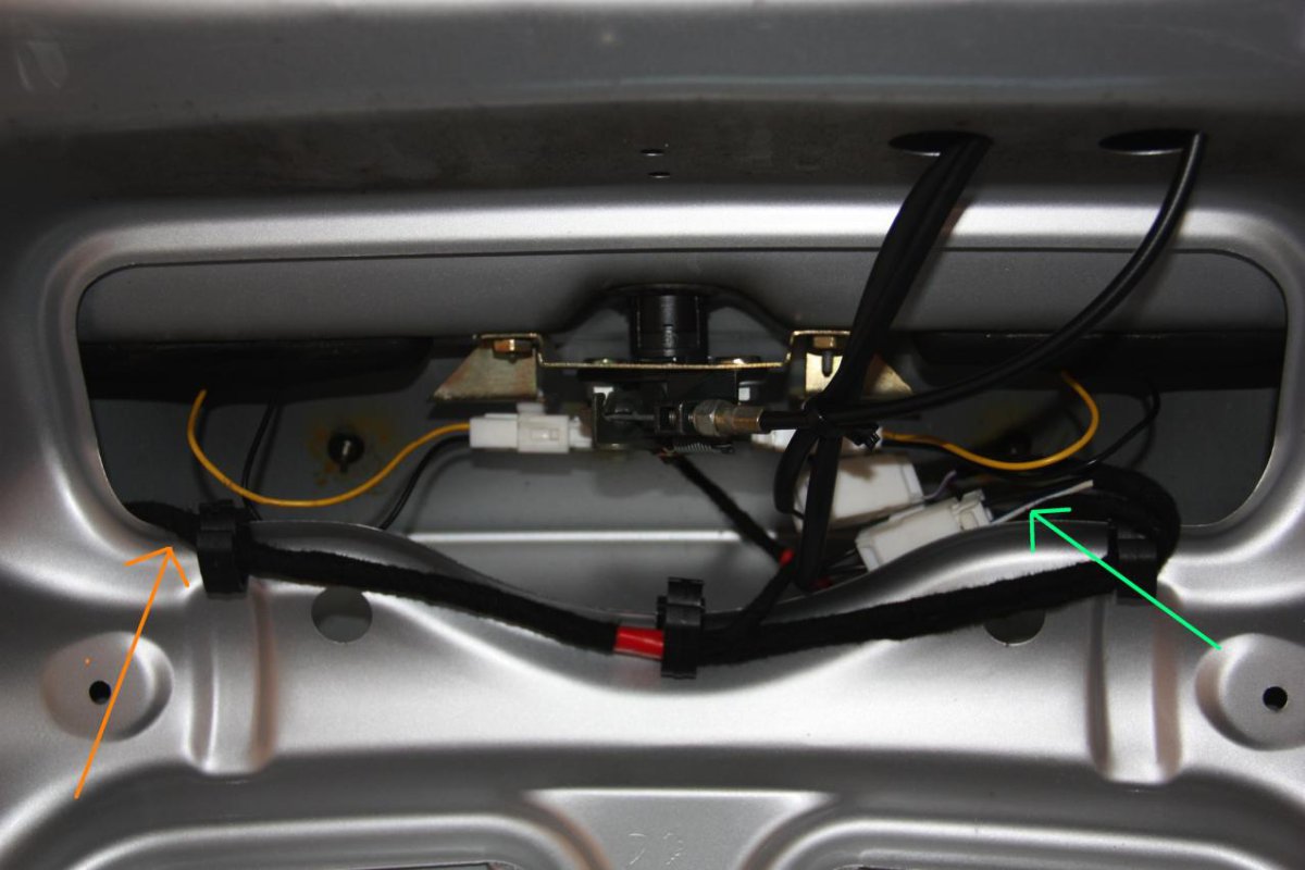
02bootlock.jpg

The connector for the boot release can be clearly seen, and the blue and white cable, arrowed in blue, is the one we need to hit with 12v to open things up. I found this out by sticking a meter on it, and getting a willing assistant to press the button in the glove box.
However, I don't *really* want to run a new cable into the boot, and through the conduit, that's just going to be hard. So where does this cable go? Find out in the next exciting installment :)

C
 
Last edited:

CatmanV2

Member
Messages
48,736
Where indeed does the cable go. Well, fortunately, my boot is currently 'au naturel' while I trace down leaks, so I've found the wire, and you don't have to :)

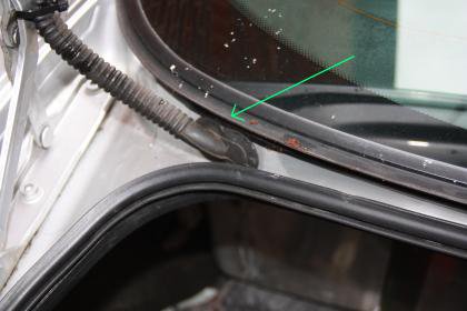
Firstly it passes through the flexible conduit marked with the green arrow:
03bootconduit.jpg

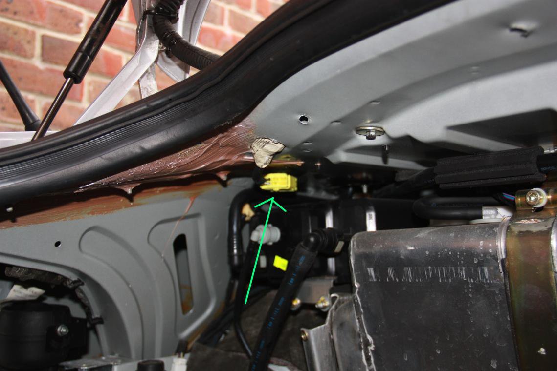
Through this yellow multipin

04bootlidconnector.jpg

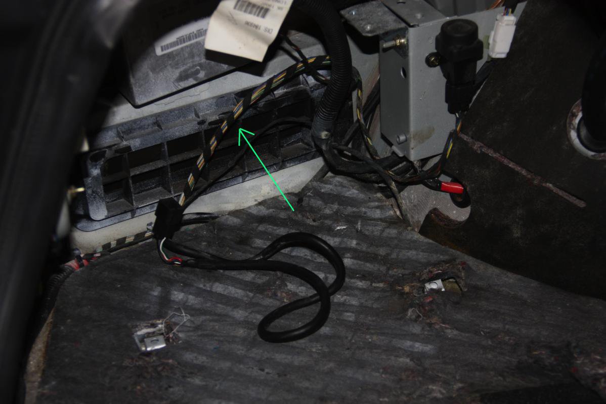
Along the nearside, rear arch

05cableroute1.jpg

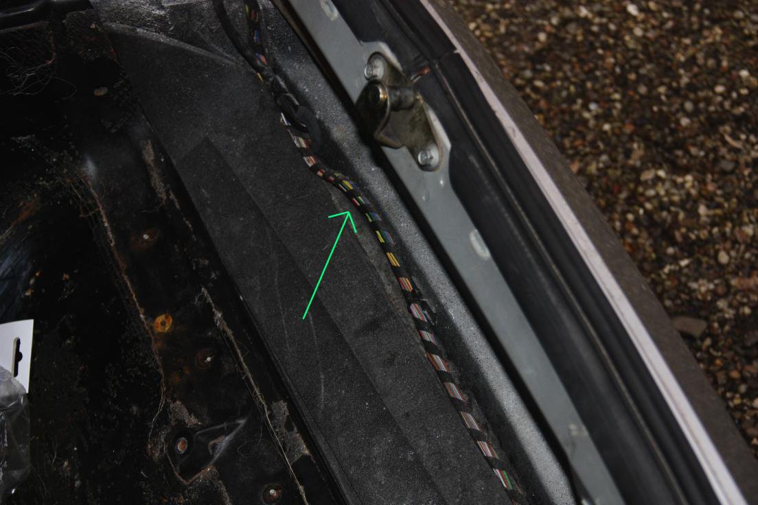
And along in the rear angle of the boot, towards the battery.

06cableroute2.jpg

Now we're getting somewhere. Nice and close to the battery for our power connections, and maybe a convenient mounting point:

07cablebundleandmounting.jpg

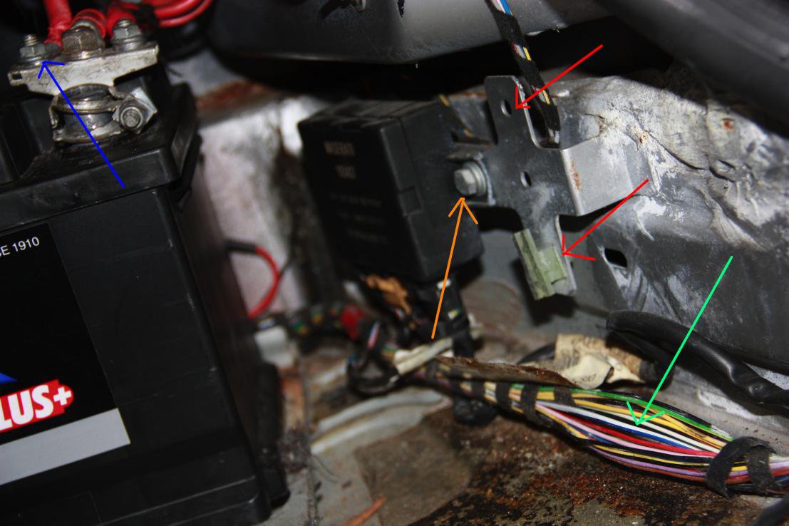
Battery terminal clearly marked in blue (bit cocked, but I fix that later) a convenient (switched) earth marked in orange, a couple of potential mounting points in red (there was a plug mount in the lower whole, but no indication of what was supposed to be connected, so I whipped it out) and the cable we're interested in arrowed in green.

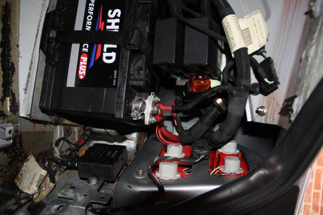
Now at this point I want to make a choice. The *proper* way to do it would be trigger the relay, located in here:

08batteryrelays.jpg

However, courage failed me. The thought of digging into 10 year old, Italian distribution blocks just presented too big a risk I felt. I knew the output of the remote is 15A, and that is plenty to drive the solenoid, so I took the easy option of feeding directly to the cable we'd already identified. So now we just need to connect everything up:
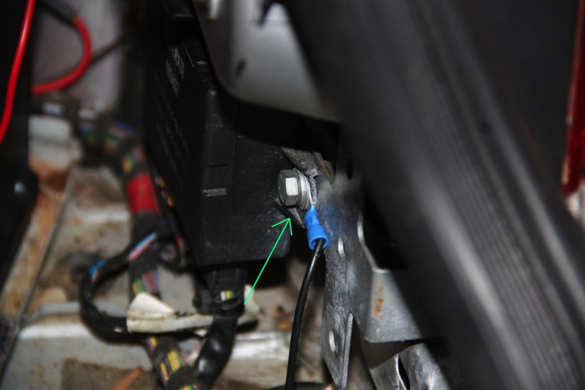
Here's the negative connection. I've used a standard crimp terminal with a 6.7mm diameter. The battery switch in these cars acts on the negative side (makes sense) so given where I am connecting, I know the remote boot will also be turned off with all the rest of the electronics. This is how I want things to work so that's good.

09negative.jpg

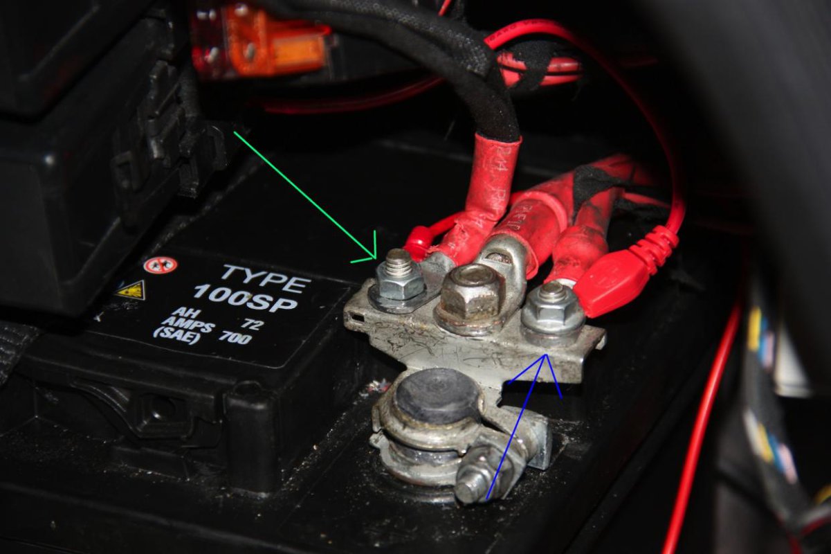
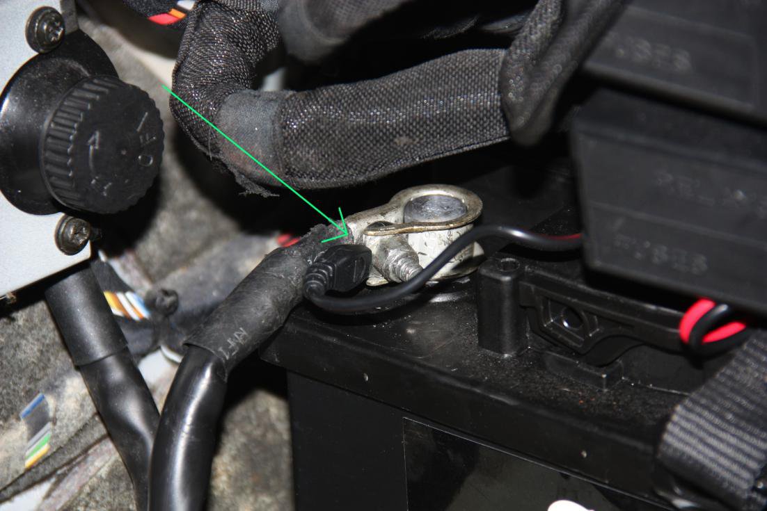
For 12v I went straight to the battery (which as you can see now has the terminal on straighter. It's a bit broke, so I may replace it at some point, but I don't think there's any real issue). The remote positive is arrowed in green. While I was in here, I too the opportunity to connect my CTEK plug, and the positive for that is marked in blue:

10positive.jpg

For the CTEK I wanted it to charge the battery even when the master switch was off, so straight onto the negative terminal then:

11CTEKnegative.jpg

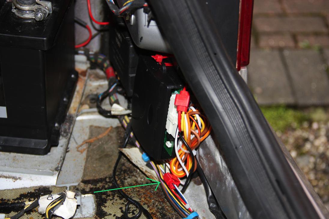
With the power connections made, I then connected the white and black output from the remote to the blue and white cable in the bundle we'd traced from the boot lid. Plugged it all in, hit the plib and Bob's your uncle :)

Finally, after testing, I mounted the unit using cable ties to the bracket I'd spotted earlier. All the cables tucked away, and a couple of additional ties to prevent the spiral wrap of the cable bundle from unravelling.

The connection to the blue and white cable is marked in green:

13finalinstall.jpg

And that's about it. I think you can reach that point by simply removing the right hand boot liner, as per V8Chimp's excellent instructions and really it shouldn't take more than two hours. from start to finish.

Tools required:
10mm ring spanner
10mm socket if you want.
Terminal crimper
Wire cutter / stripper.
Meter would be good to test.

And that's it. We will now take questions from the assembled classico owners :)

C
 
Last edited:

Almichie

Junior Member
Messages
799
I wonder if the 3200 wiring loom would be the same - you would think so wouldn't you?
 

CatmanV2

Member
Messages
48,736
Personally I'm not sure I'd chance it. Putting 12v down a random wire cos it's the right colour for another car is possibly contra indicated :)

C
 

Klive

Junior Member
Messages
724
Ahh, now I understand what you were talking about. This is a good clear "how to" for someone else to follow.
 

SpyderNick

Junior Member
Messages
326
Great How to, Catman.

Do you happen to know if any of the outputs will give a continuous, 15 amp output whilst one of the remote buttons is held down ?
or even if 2 would do that ?
 

CatmanV2

Member
Messages
48,736
Great How to, Catman.

Do you happen to know if any of the outputs will give a continuous, 15 amp output whilst one of the remote buttons is held down ?
or even if 2 would do that ?

No, the outputs are switchable for 0.5 or 3.5 seconds (I might update things to reflect that) Mine is on the default of 0.5s as that's far more than the solenoid needs.
Having said that it would be trivial to add a couple of components to give you 'press on' > continuous 15 A > 'press off' functionality if that would help.
Can I ask what you're trying to achieve? I may be able to think of simpler way for you.

C
 

SpyderNick

Junior Member
Messages
326
Hi Catman,

I am thinking about a remote for the Convertible roof. It would need 2 continuous powers one for open and one for close.
If using single bursts then I am thinking that I would need 2 channels on and off for each of 2 relays, so 4 channels in all.
But that is then getting into a full on project in my eyes rather than just power to each side of the roof rocker switch.
If you have any other ideas on a simple solution I would be very interested.
I also haven't checked if the roof is powered with no key inserted yet, but will check that this morning.
 

CatmanV2

Member
Messages
48,736
Hmm, OK, this ties into the mirror retract that I was thinking about.

Let me have a think as I can't really articulate what I see to be the issue here...

It could be done, but I think the switch / fusebox interface will be the way to go, though.

C
 

SpyderNick

Junior Member
Messages
326
Ok,

Now that's a good idea as well,
I hadn't thought about retracting the mirrors remotely, although I have thought about having them retract when the car is locked.
I am just changing one of the door mirrors so I will be checking that out now when I go down to do some checking of the roof switch.
 

CatmanV2

Member
Messages
48,736
Two challenges with the door mirrors:
1) They stop if you turn the ignition off while retracting, so they are not self powering.
2) They stop if you let go of the button.
3) Does the switch continue to supply 12v while being activated, even if the mirror has reached its extreme?

I'm still thinking about it, but it seems a bit of a biggy:

Perhaps you can check on point 3 while you have it all in bits, Nick?

C
 

mjheathcote

Centenary Club
Messages
9,038
If you have a search on ebay, you can buy single, and multiple channel remotes. They also have various delay options, and I have seen one with an on and off button that sounds perfect for a remote soft top control.
Don't search for central locking remote systems, more 'single channel remote' etc.
Cheers.
 

CatmanV2

Member
Messages
48,736
OK, so after some pondering Nick, here's what I think the situation is (anyone who wants to shoot me down in flames, go for it;))

1) Do you want to open *and* close the roof remotely? If so, then as near as I can tell you'll need two channels. It could be done with one channel, but I think you'd need some kind of feedback to tell the system if it's open, or closed, and that way madness lies.
2) Do the roof controls operate with the ignition off. Pretty pointless a project if not, but.... I suspect you're going to run into something of an issue here, same as with the mirrors. You'd need to de-couple the system from the switched 12v and connect it to permanent 12v. There's a minor additional risk there that any fault may happily drain your battery.Doing that without de-coupling other bits may be overly complex. I can't even find out from the workshop manual where the relay(s) that control the roof are, so at this point it's a bit hard to estimate how hard.
3) The final bit: *Simplest* way to do this would be to duplicate the switch function (or at least the close aspect) using a relay driven by the remote. That would be quite simple if I could get hold of a switch to see what it is, and we could get over point 2.

Does that help at all?

C
 

SpyderNick

Junior Member
Messages
326
Hi Catman,
Sorry I was about to post earlier.
I couldn’t get the switch or the Mirror switch panel to pop out so I had to remove the entire central console.
I’ll come to 1. In a minute.
2. The roof is the same as the mirror so will require a separate 12v supply. I saw one in the well under the armrest that is part of my parrot Bluetooth setup, I also think that there must be one to the NIT as it will run without the ignition being on. This I believe is good place to put any remote relay.
The roof switch is just a rocker connecting between either the open wire or the close wire. I have connected to the 12v and each of the other 2 wires and run this to under the armrest ( there is also a negative but is not used). I have tested just touching the 12v to each in turn and operated the full open and close procedure.
After looking at the mirror panel connector I think that this works in exactly the same way, it is just necessary to identify the correct wire (possibly 2 if each mirror works independently.)
3. I agree that all that is needed is a remote and relay for each function (Open. Close, Fold)
1. I think that a 3 channel remote/relay is all that is needed and can be connected by attached wiring in the armrest well.
So a 3 channel 12v remote that operates 3 12v relays. The ones I see on eBay seem to have 12v / 240v on the relays and I’m not entirely sure if they will switch the 12v, I need some help on that.
Removing the central console to get at the switch plugs/wires is about a 15 minute job so not really a major issue if you can’t get the switches out, my plug wires are just too short.
 

CatmanV2

Member
Messages
48,736
Groovy, thanks :)

Have you got a link to one of the ebay units?

The output type would depend on if you can use one relay, or you'd need two.

With the mirrors, you can get away with using one of the alarm channels as 3.5 sec is ample. I probably wont though, as I CBA to run the control from the boot, now.

Aside: Did you install your Parrot? I'm hoping to do one next month.

C
 

SpyderNick

Junior Member
Messages
326
here's a link to 1 4 channel unit,

http://www.ebay.co.uk/itm/12V-4-Cha...60795972645?pt=UK_Gadgets&hash=item3cb8a6bc25

I need to understand which units will cope with 15Amps and also ones that have "spot move" mode which I assume give one press for relay close and the next for relay open.
this is from the manual, but this one only seems to cope with 7Amps

Specification: Working Voltage: DC 12V Receiving Frequency: 315mhz/433mhz
Receiving Sensitivity: -95db
Working Mode: Spot move, mutual-lock(option:self-lock)
Max. Load: 7A
Coding Types: learning
Coding Mode: Welding torch
Working modes
Working mode Description
spot move press button--ON;release button--OFF
self-lock press button--ON;press this button again--OFF
mutual lock press button A--ON;press another button--OFF

I think I need one similar but one that will cope with 15amps ?
 
Last edited: