

Hi there,
Can anyone please help me to understand how the small cooling circuit works? The big one (engine) is fairly simple, the small (HVAC) one is not.
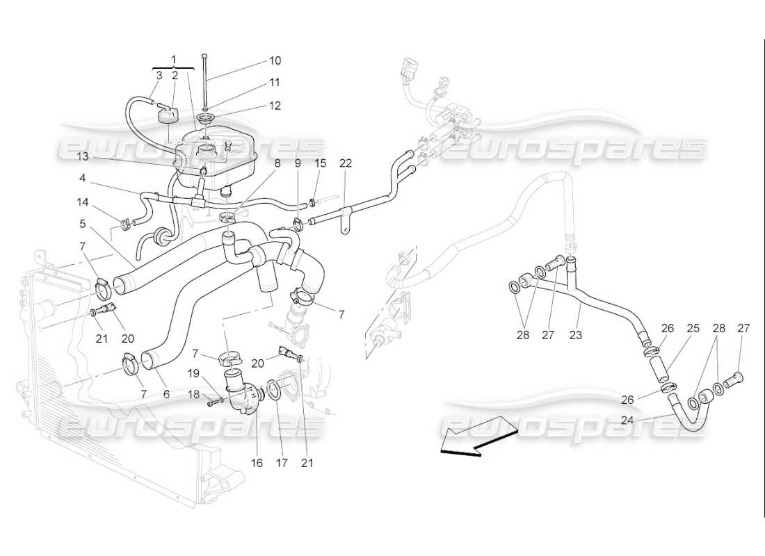
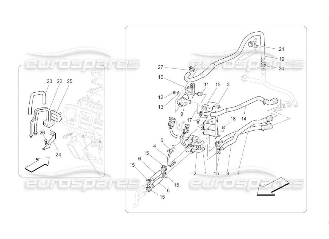
If I got that correctly, it all starts with a branch from the big circuit (item 22 upper, all pictures below). The branch is then split into two parts (upper and lower) and both connect to a dual-valve (called TGK?). Next both lines connect to the firewall and disappear.
But there also is a line returning from the firewall (item 14 lower). It is connected to an electrical water pump (9 lower). Its output is forwarded (by 19 lower) to a T-junction (item 23 upper). Both ends are connected to something (to each cylinder head, maybe..?).
Where am I right and where am I wrong? In which direction does the water flow? What do the TGK valves do? And what happens behind the firewall (in the HVAC, I guess)? What is the return line (item 14 lower), which is connected to the electrical water pump? And what does this pump supply, is it really the cylinder heads?
Thanks for any help!
Jaz
Picture 023 - Cooling System: Nourice And Lines:
Picture 080 - AC Unit Engine Compartment Devices:
Can anyone please help me to understand how the small cooling circuit works? The big one (engine) is fairly simple, the small (HVAC) one is not.
If I got that correctly, it all starts with a branch from the big circuit (item 22 upper, all pictures below). The branch is then split into two parts (upper and lower) and both connect to a dual-valve (called TGK?). Next both lines connect to the firewall and disappear.
But there also is a line returning from the firewall (item 14 lower). It is connected to an electrical water pump (9 lower). Its output is forwarded (by 19 lower) to a T-junction (item 23 upper). Both ends are connected to something (to each cylinder head, maybe..?).
Where am I right and where am I wrong? In which direction does the water flow? What do the TGK valves do? And what happens behind the firewall (in the HVAC, I guess)? What is the return line (item 14 lower), which is connected to the electrical water pump? And what does this pump supply, is it really the cylinder heads?
Thanks for any help!
Jaz
Picture 023 - Cooling System: Nourice And Lines:
Picture 080 - AC Unit Engine Compartment Devices: